Asimov J-29: My 3D Printed Computer
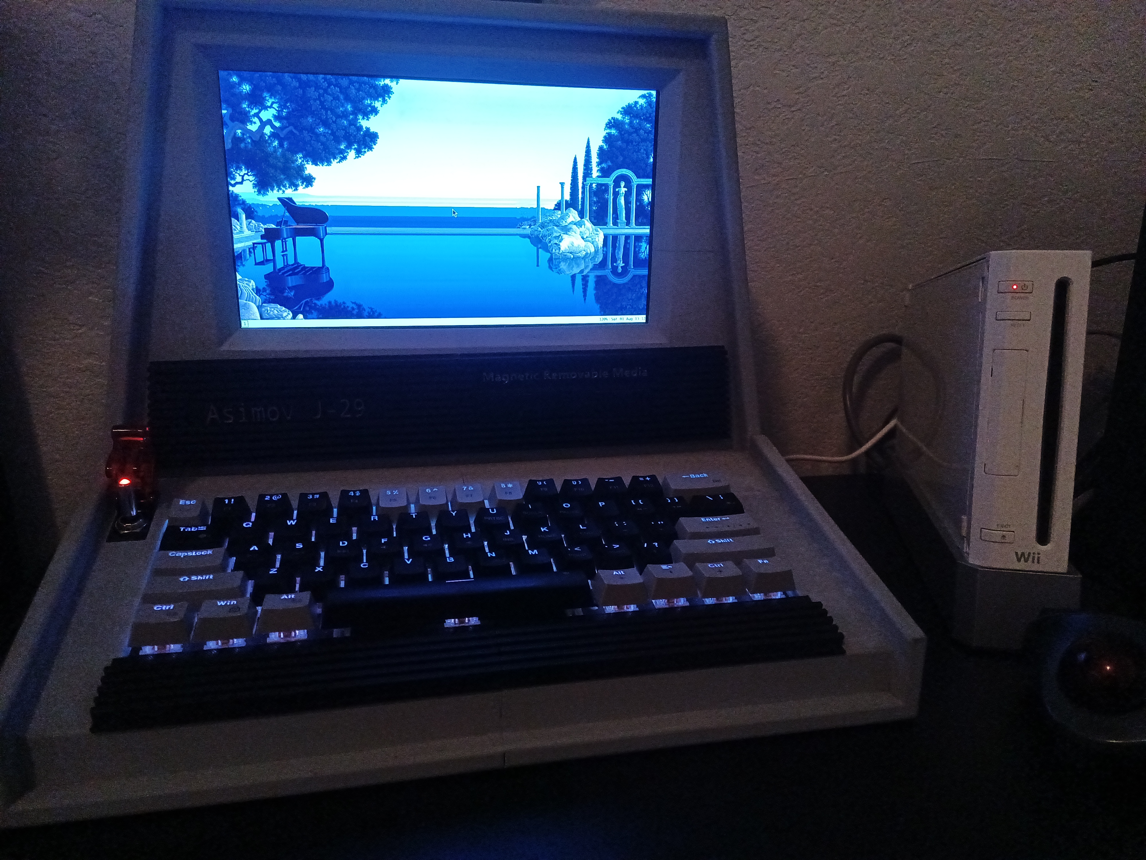
To build this computer, I used about 2 kilograms of PLA filament. Honestly, you can use any plastic filament of your choice. Brand and color really doesn’t matter. I won’t go too much into the 3D printing specifics but I’d recommend using whatever works well on your printer. You can save some money and use your leftover spools which is what I did (mostly gray PLA).
Once you have it all done, you can put it all together using the printed tabs provided in the files, super glue the pieces while you are at it and be done with the chassis but I wanted to make mine look a little nicer so I used some Bondo filler and sand paper to smooth out the chassis and try to hide the seams as best as I could (I honestly didn’t do a great job but it makes it look less like it was 3D printed). From there, I took it outside in the boiling hot sun and gave it a matte gray coat of spray paint. It was dreadfully windy and I live near a field so there’s dust and shit always flying in my direction and running my paint job but I got it to a point where it looks okay.
As a little extra, a user by the name of Perihelion_ made some trim parts for this specific PC model which I used to add a front cover, name tag, and a bit of the keyboard bezel which didn’t fit on my printer. To get it done, I had to split the model in Orcaslicer so that I can print the large parts separately and then glue them together. The front plate was printed in a basic black PLA while the keyboard bezel was done in TPU so it could work like a soft squishy palm rest while you type. I modified the name tag to “Asimov J-29” as a reference to my initials and then used a chrome marker to highlight the text.
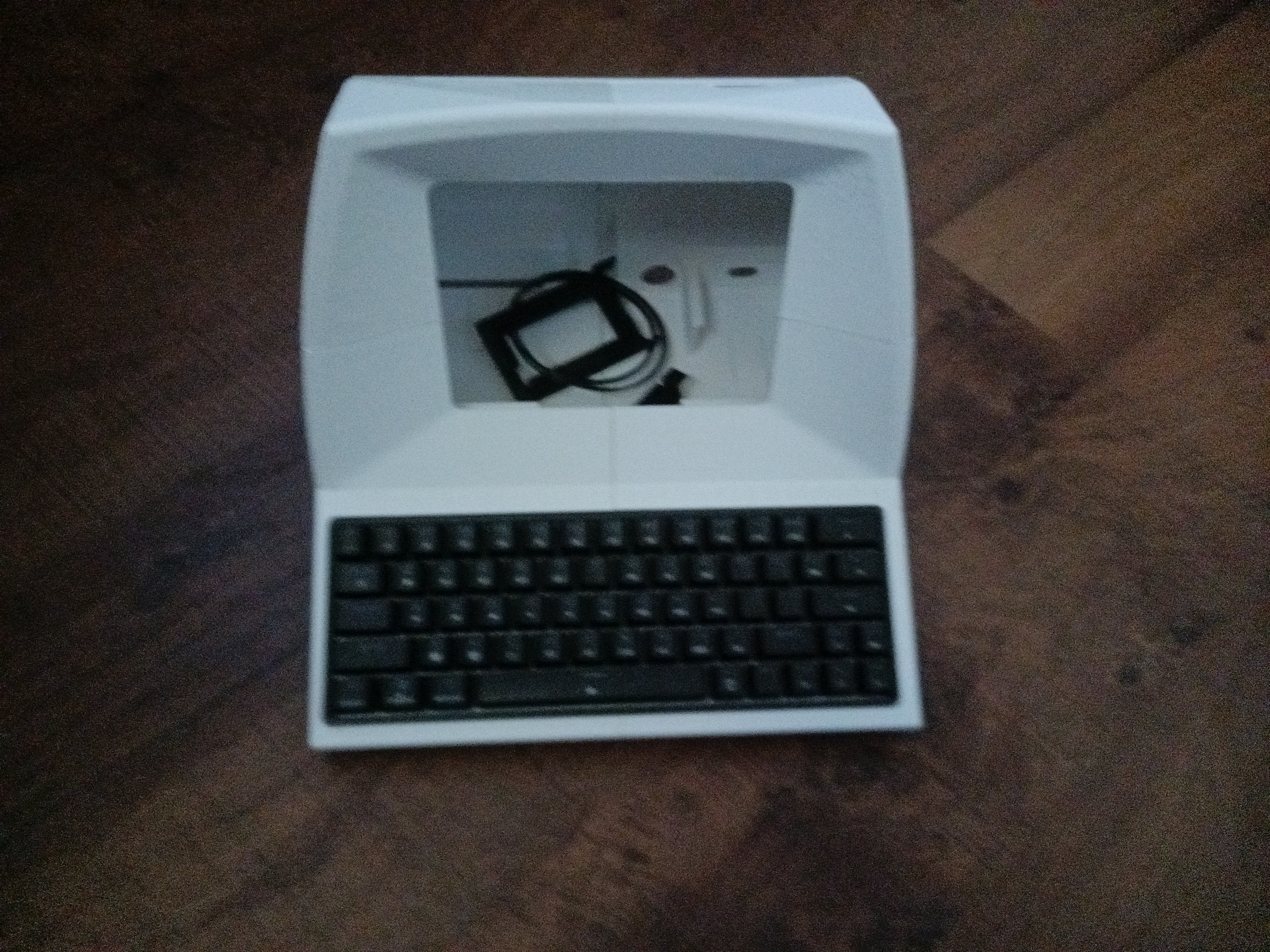
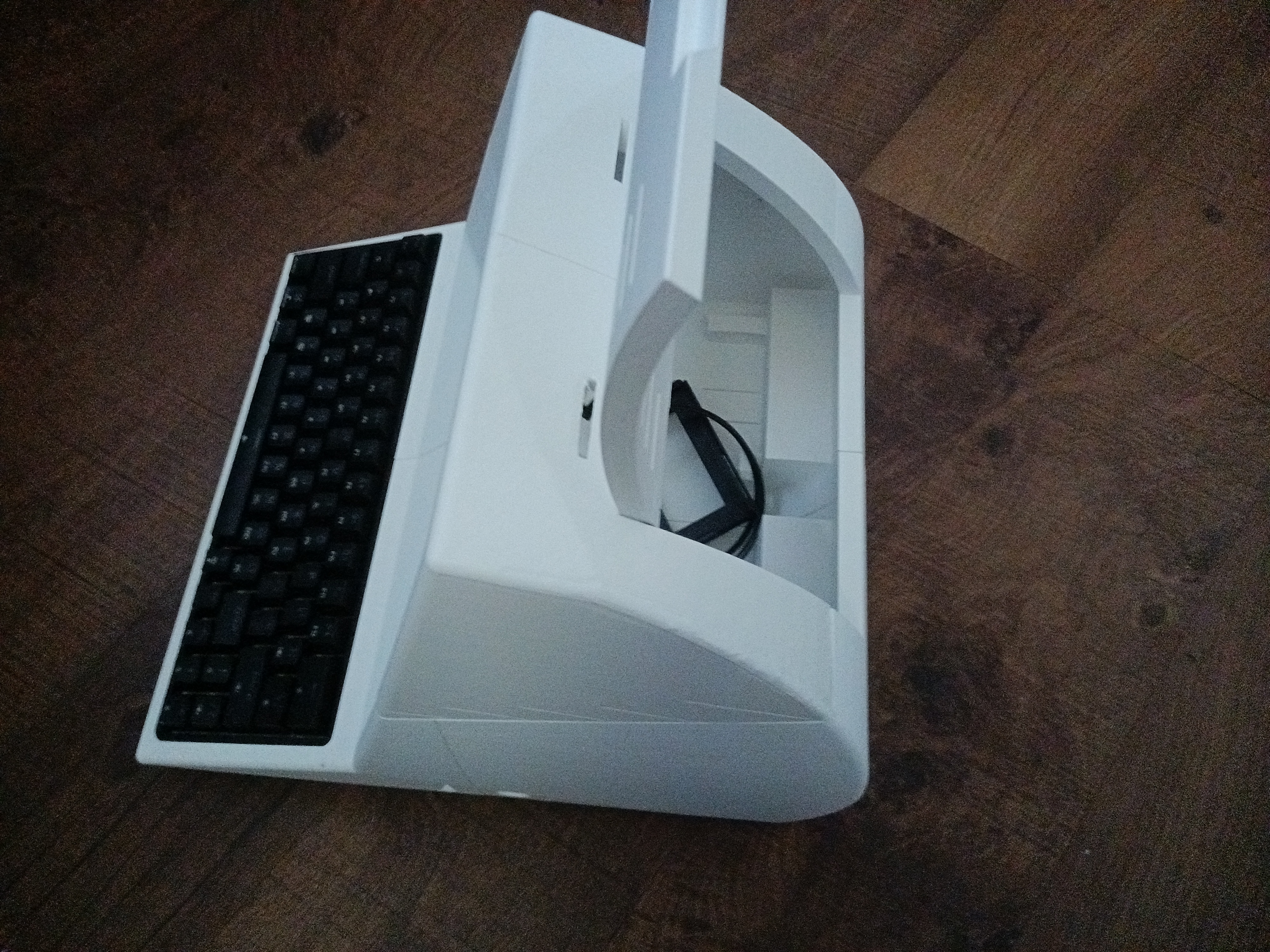
The hardest part of this build wasn’t so much building the chassis but finding the parts to make it work. Most of the links are from Amazon but a lot of the parts listed are no longer available in particular the screen and the keyboard. To get around this, I had to improvise. I had an Aula 60% keyboard that I gutted to shove into the chassis keyboard slot. I used duct tape to create a soft padding on the bottom of the keyboards motherboard so that the keyboard won’t flex too much while I type on it. The screen I used was a 10.1 inch iPistBit screen. It has all the ports I need like HDMI, built in speakers micro usb, and an aux port that I can use for headphones. The one problem is that the dimensions on this screen are smaller in terms of length and width compared to the recommend screen. I got creative and used the stands that the screen comes with to hold up the screen and glued those to the chassis. I then used a mix of automotive double sided tape, electrical tape, and duct tape to secure the screen in place once it was centered where it needed to be. It’s not perfect by any means but I got it done and the screen looks good from my view. I also got the USB hub, automotive switch, and external Floppy Disk Drive listed in the build list but skipped out on the Ethernet port because I wasn’t going to use that for my build.
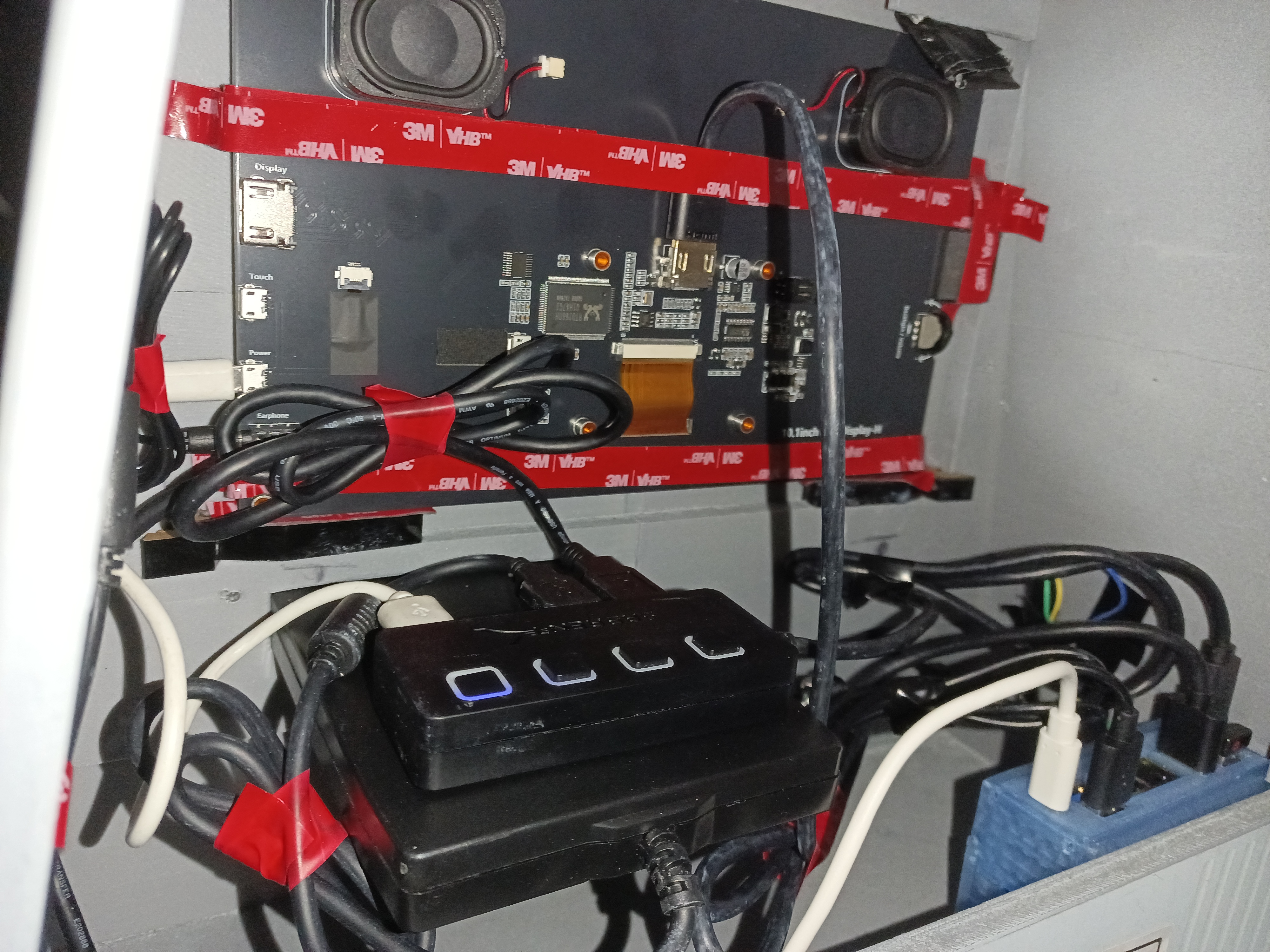
Initially, I used this chassis with the screen and keyboard as a backup monitor for my desktop. While it is more usable than you might assume, it’s not ideal. Some programs with a lot of UI elements like Bitwig studios will not function properly because of the small screen. Using GIMP on such a small screen is a real nightmare and some bloated websites are kind of hard to read. Minimalist websites or those with not too many elements on screen are perfectly fine. You can even game on it though it depends on the kind of game you’re playing and if it’s designed to work well with a small 10.1 inch screen.
Eventually, I settled for using an Orange PI RV2. Raspberry Pis were and still are way overpriced for what they are so I went with the cheapest alternative at the time. The Orange Pi RV2 is not your typical ARM SBC that you can run retropi and have a cheap emulation device. It’s an entirely experimental board running off RISC-V hardware that has a lot of interesting perks such as being free and open source. It’s cheaper for manufactures to make RISC-V. As far as I’m aware, there are no glow in the dark back doors like you would have with Intel or AMD CPUs. Of course, this comes with the caveat that this cpu architecture is fairly new and thus doesn’t have all the compatibility or support of x86-64 or ARM. Don’t buy into RISC-V hardware unless you have some experience with ARM SBCs. I would have used my old Raspberry PI 3B+ but it stopped working a while ago and I had no way to use it for this project. I used a 27W 5.1V/5A USB-C Power Supply which worked fine for my orange pi and everything else I had to power. The Orange PI RV2 comes with a wifi antenna and Bluetooth capabilities out of the box as well as a port for M.2 M-Key SSDs but I don’t have one of those.
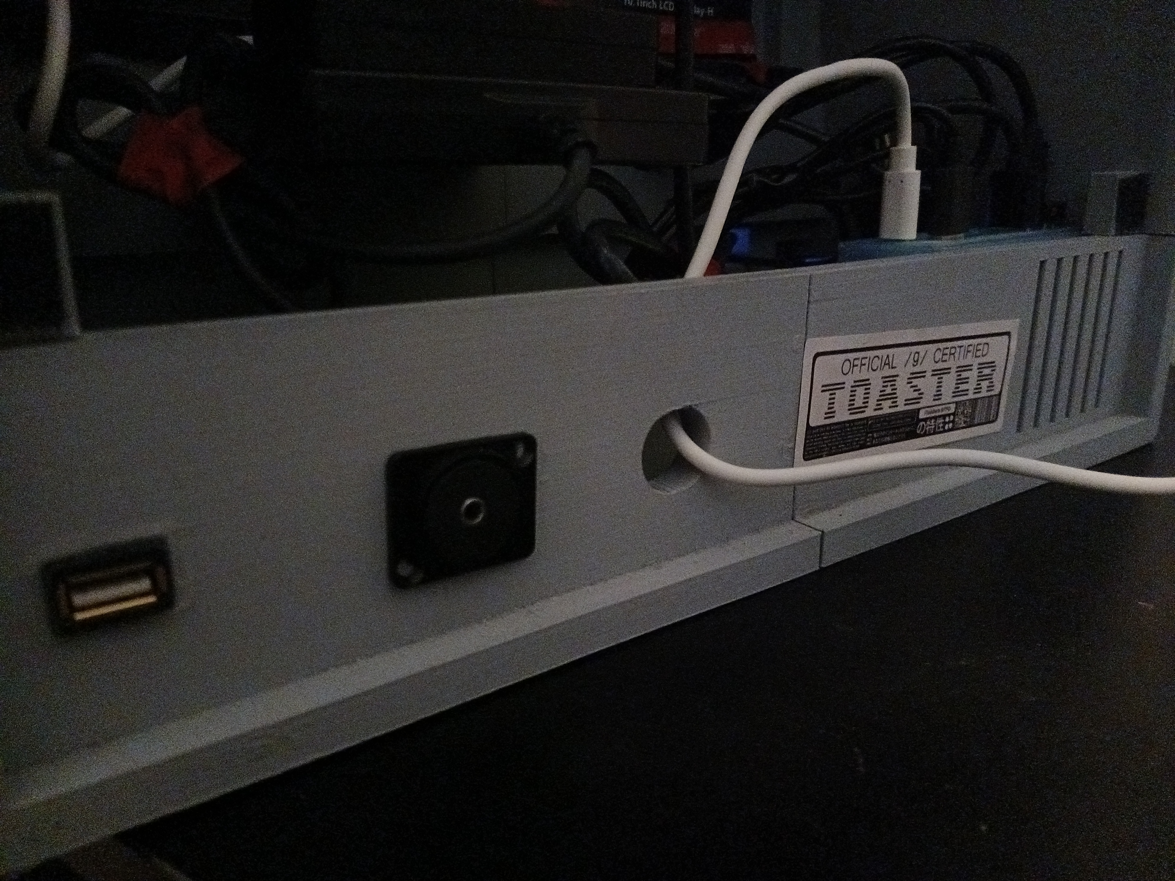
I don’t think I used any screws for my project. I have some but everything internally is held in using double sided tape, glue, or electrical tape. My Orange PI RV2 has a PETG case that I printed for it so it can use a small cpu fan to keep it cool and then I used double sided tape to attach it so that the top of the board and the fan is against the air vents on the chassis. I didn’t have any zip ties with me so I used electrical tape to manage the cables connecting to the Orange PI and make things as neat as I can. The external floppy disk reader fits right into the slot dedicated to it on the chassis and I used the USB hub to connect the monitor, floppy disk reader, and external USB extension which is snaked over to the back so you can plug in an external USB device. There are two other holes, one of which I used an aux female to female coupler to serve as my headphone jack. A 3.5 mm male to male cable connects to the aux of the monitor to the coupler so that’s how you can use headphones on this computer. The last hole can be used for whatever but I have my power supply cable going through it for now. In the future, I will use a USB C female to female coupler so I can make it more seamless and polished. I’m using a wireless Logitech trackball mouse with the receiver on the Orange Pi’s USB ports alongside the cable that connects to the keyboard. I think that sums up most of the computer hardware I used.
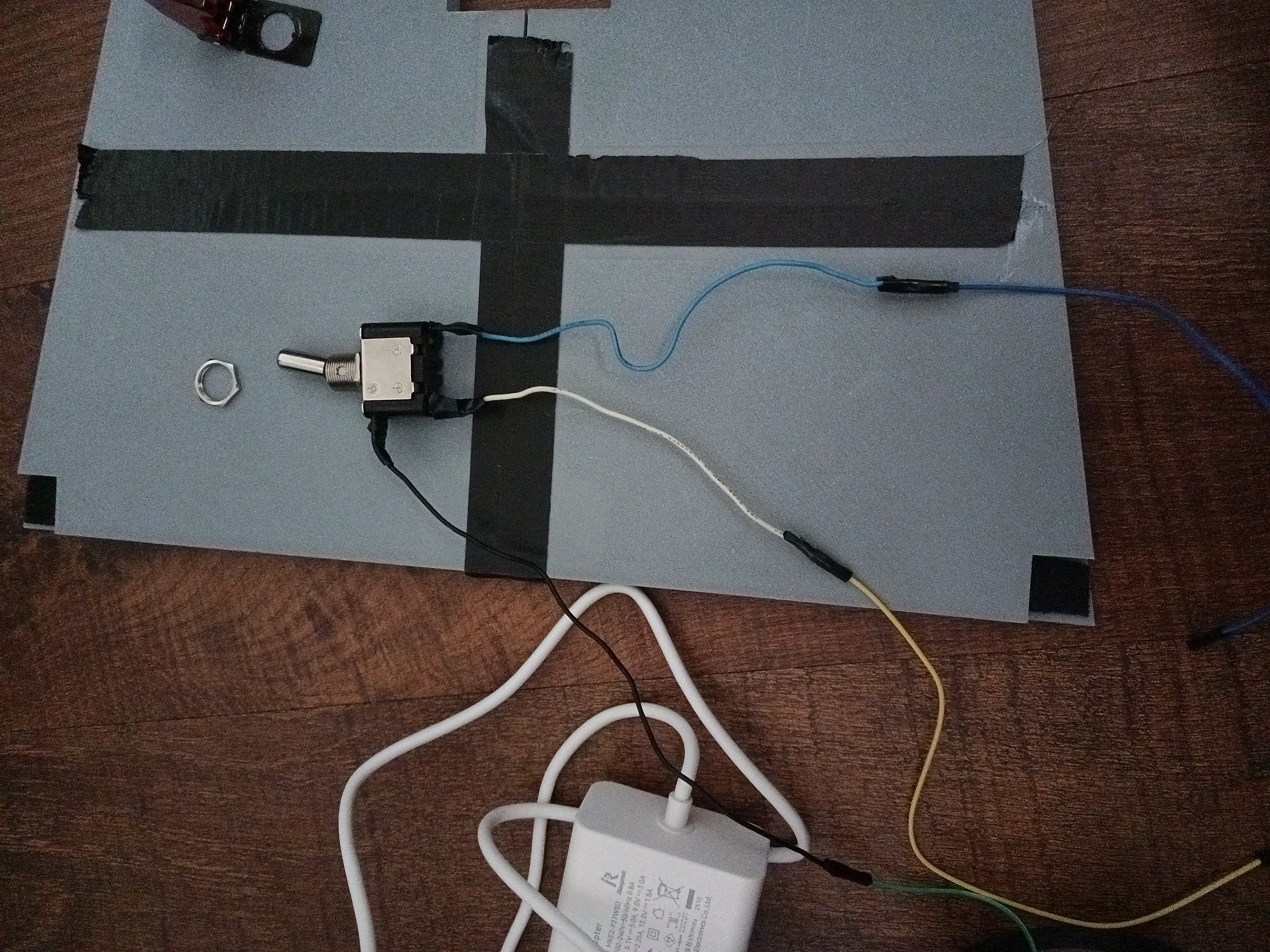
The next hardest part was getting that automotive switch that is used on the chassis to do something. While having a switch like this is not a requirement for this build and arguably unnecessary considering the only real way to turn off this computer is to remove the power supply every time you want to power off the SBC. You can theoretically splice some wires from the switch to the power supply cable itself and have a physical kill switch that way but I don’t have a working soldering iron and that sounds incredibly tedious. Instead, I used some of my electrical wires and jumper wires to connect a series of wires in conjunction with a 1 kilo-ohm resistor to wire the switch to the GPIO points on the Orange Pi and then used a custom Python script to initiate a shutdown sequence whenever the switch is moved to the off position. Again, I don’t have a working soldering iron but using jumper wires and splicing helped get this feature up and running for /etc/systemd/system/. I saved this script as “gpioshutdown.service”.
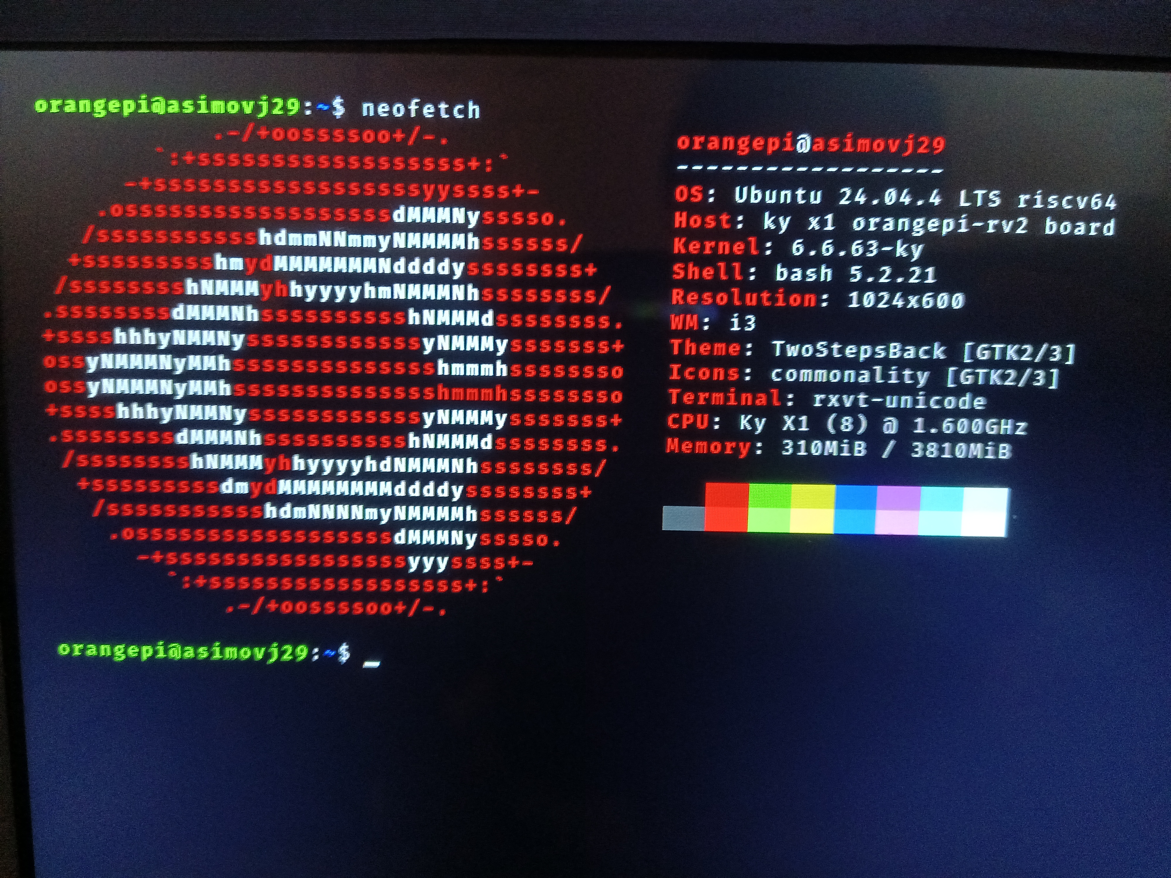
There’s not a lot of distro options for RISCV, let alone for this Orange PI RV2. I’ve tried everything from a Debian build that refuses to boot, an Arch based distro that doesn’t work either, and the default official Ubuntu build for the RV2 comes with Gnome which is sluggish and horrible to use in general (I hate Gnome 3). Instead, I suggest using the Ubuntu Server build so you can install whatever packages you desire. I know Ubuntu isn’t everyone’s favorite and it’s certainly not mine either but this is all you have to work with this SBC. I have I3 WM with xorg and lightdm as my login screen. My configs for i3 are almost the same as my laptop’s config but there’s no need to have a battery script. On idle, it uses only around 310 Mib out of 4GB. Not bad at all. Packages are severely outdated on this build of Ubuntu. Hence why I’m using Neofetch for this image:
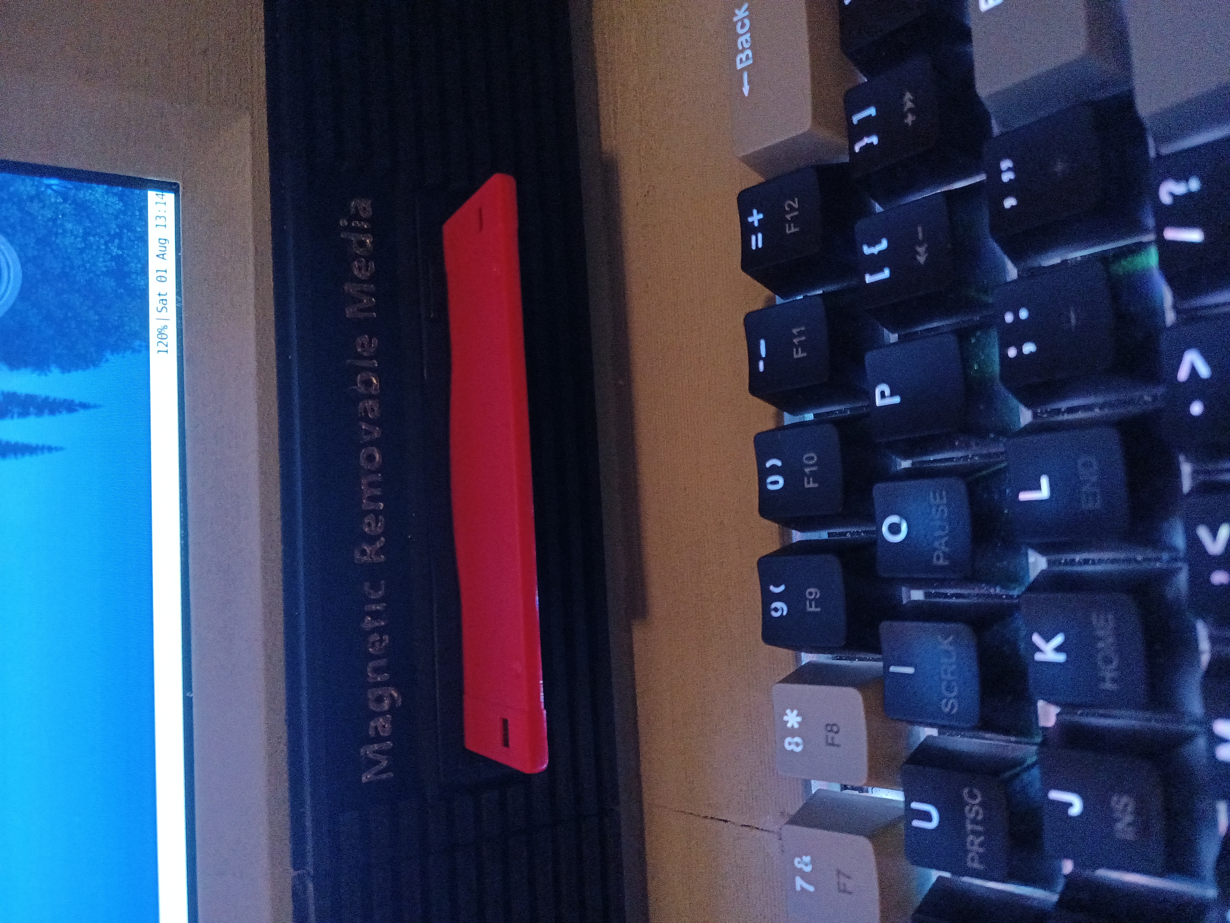
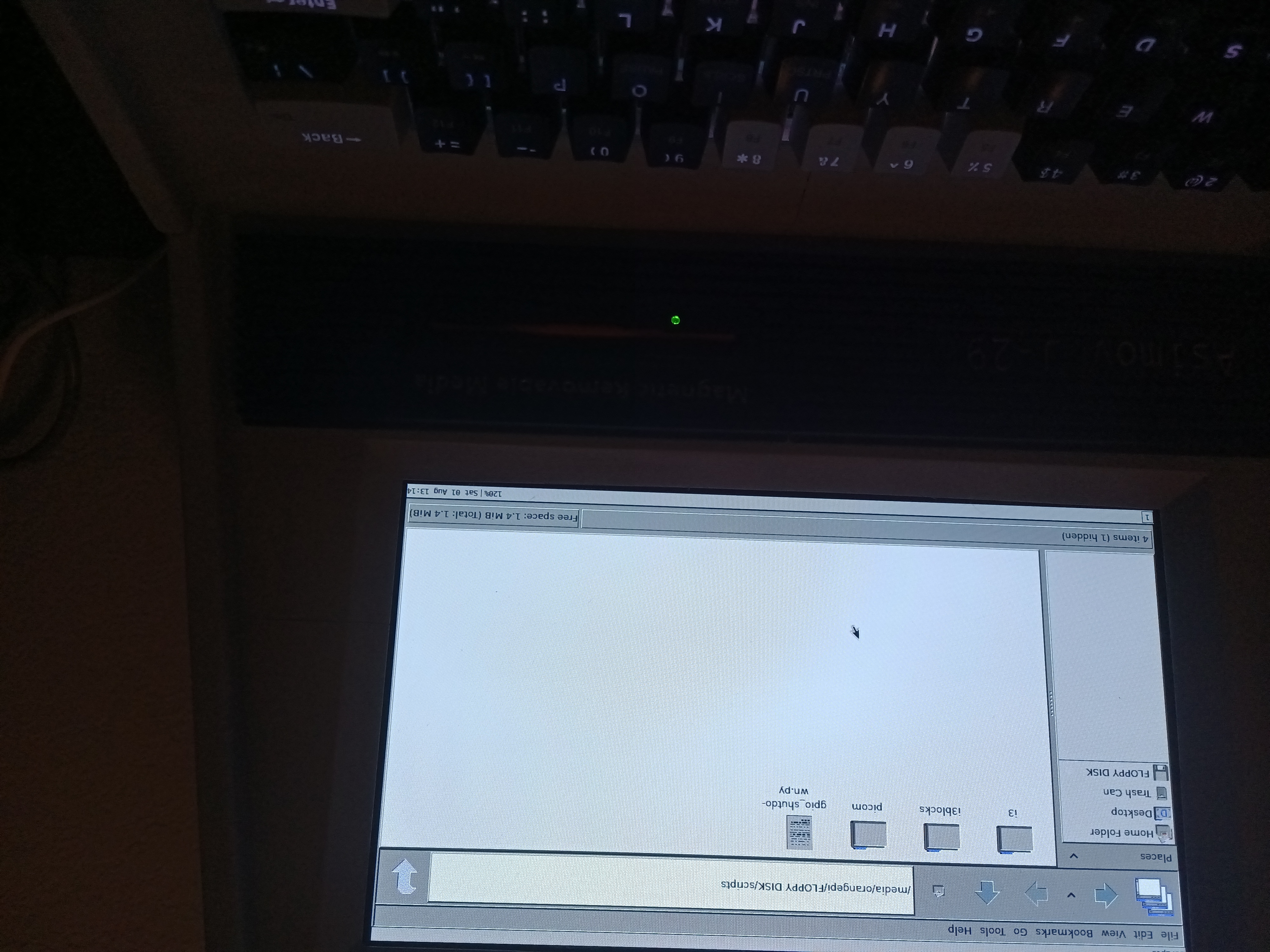
The floppy disk reader is very power hungry hence why I am using the USB hub. You cannot have it on while you boot into the operating system. Instead, you will have to open the back panel and press the button where the drive is connected after you boot into the operating system. From there, the floppy disk reader works as advertised.
Originally, the panel was supposed to be screwed in from four corners, but to keep it accessible and have the entire build screw-free, I used sticky Velcro squares so that you can pull on the back to remove and re-attach the panel. This makes it easier to access that USB hub so can power on and off additional hardware or do some maintenance on the internals.
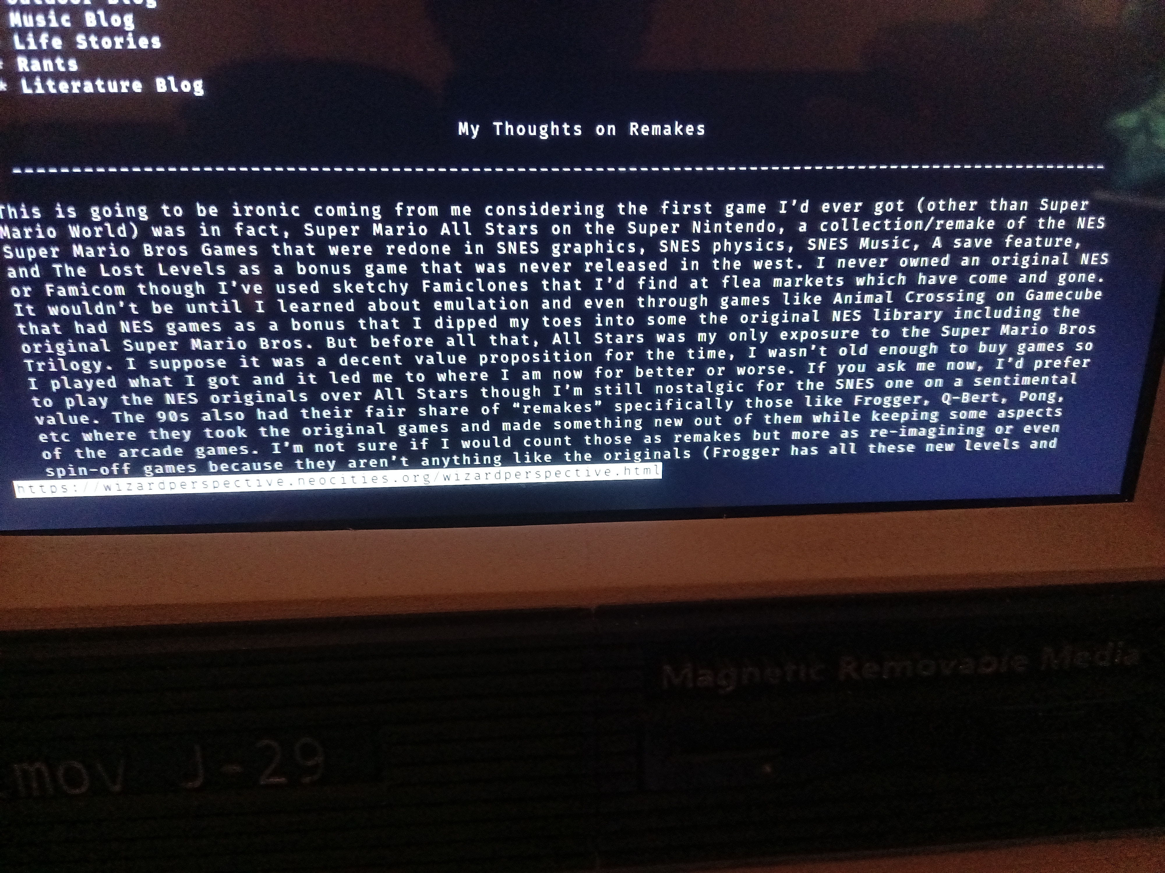
I have been using Neocities CLI to blog directly from a terminal by editing my files with Kakoune and then updating them to my website. I can also listen to music with cmus, watch sub-720p videos with MPV, browse a minimalist web through terminal or xorg using links2, do some office work with libreoffice, and play crispy-doom albeit with some audio stuttering but overall decent performance (RISC-V gaming is still in its infancy so performance isn't great to begin with). I also messed with VICE which is a Commodore 64 emulator and tested out a few BASIC programming commands that I read from a PDF guide from an old scan.
It took about a year since I started the project but only because I was in NEETdom and didn't have the funds to buy the parts I need. Now that I have somewhat of an income, I was able to finish the project though not to original specifications. It's not perfect as I knicked the top corner of the PC and my wiring could be better. The only thing I really have left is to fix that blem on the top corner, perhaps apply some kind of vinyl covering if possible to make it look nicer, and add a USB coupler to the back like I did with the headphone port so I can plug the power supply directly from the outside instead of through a hole.
Do I recommend this build? Hm...not really. As I mentioned before, the parts specified for this build aren't available nor easy to obtain. You can get creative like I did and try to make it work. But what I would recommend instead is to go for the Callisto 2 and a half (Remix) by Tinkering_On_Steroid on Thingiverse. The build list is more up to date with parts that you can easily find and this particular build uses a more historically accurate 4:3 display instead of 16:9 on my build. I've already finished printing the chassis on this build but there's a lot of work that has to be done before it's complete.
Honestly, we should go back to the 70s and early 80s era of the PC hobby. Back in those days, you had to assemble the PC and solder everything yourself. While I didn't really do any soldering on this 3D printed computer, It would be cool if I could do an entire motherboard from scratch. Why stop there? If I were smart and dedicated enough, why not develop an entirely new operating system? I'm no Terry Davis but that's something that more "tech" people should consider.
Return to Catalog